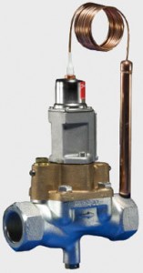
Thermostatic valve Type WVTS
Thermostatic valve type WVTS is suitable for controlling the temperature of a flow of water or neutral brine.
WVTS opens on rising sensor temperature and is indirect servo operated thermostatic valve. It is suitable for controlling temperature in industrial applications by regulating the quantity of cooling water or neutral brine that
cools down the process. The valves are self-acting, i.e. they operate without the supply of auxiliary energy such as
electricity or compressed air. The required temperature is maintained constant without unnecessary use of cooling
water in cooling systems. The operating economy and-efficiency are maximized.
 Features
Insensitive to dirt
Insensitive to water pulsating pressure
Proven reliable through decades
Easy to service
Built-in pilot filter
Long lifetime
High performance
Very high capacity
Both welding and thread connection flanges
| Technical data | |
|---|---|
| Type | WVTS for neutral media |
| Operation | Servo-operated |
| Sensor side | |||
|---|---|---|---|
| Temperature range | 0 – 30 °C | 25 – 65 °C | 50 – 90 °C |
| Max. sensor temperature | 57 °C | 90 °C | 125 ° C |
| Liquid side | |
|---|---|
| Media | Fresh water, neutral brine |
| Media temperature range | – 25 – 90 °C |
| Permissible working pressure PB | 10 bar |
| Max. test pressure | 16 bar |
| Opening differential pressure | WVTS 32 – 40: min. 0.5 bar; max. 4 bar WVTS 50 – 100: min. 0.3 bar; max. 4 bar |
Valves are supplied with capillary tube gland. Different lengths of capillary tube are available. If WVTS is required with an opening differential pressure of 1 – 10 bar, the valve servo spring must be replaced. See “Ordering”.
Ordering
| WVTS components | |||||
|---|---|---|---|---|---|
| Valve type | Connection | kv value2 [m3/h] | Code no. Valve housing | Code no. Flange set 3) | Code no. Special servo spring for differential pressure range 1 – 10 bar |
| WVTS 32 | G 1 1/4 | 12. 5 | 016D5032 | 016D1327 | |
| WVTS 40 | G 1 1/2 | 21.0 | 016D5040 | 016D0575 | |
| WVTS 50 | 2 in.weld fl. | 32.0 | 016D5050 | 027N3050 | 016D0576 |
| WVTS 65 | 2 1/2 in. weld fl. | 45.0 | 016D5065 | 027N3065 | 016D0577 |
| WVTS 80 | 3 in. weld fl. | 80.0 | 016D5080 | 027N3080 | 016D0578 |
| WVTS 100 | 4 in. weld fl. | 125. 0 | 016D5100 4) | 027N3100 | 016D0579 |
 1) ISO 228-1.
2) The kv value is the flow quantity of water in [m/h] with a pressure drop across the valve of 1 bar, p =1000 kg/m³. 3
3) Code nos. include 2 flanges.
4) Code nos. include valve housing, flange gakets, flange bolts and screws for pilot valve.
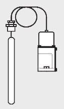
| WVTS, thermostatic pilot element 1) | ||
|---|---|---|
| Range [o C] | Capillary tube length [m] | Code no. |
| 0 – 30 | 2 | 016D1002 |
| 25 – 65 | 2 | 016D1003 |
| 50 – 90 | 2 | 016D1004 |
| 0 – 30 | 5 | 016D1005 |
| 25 – 65 | 5 | 016D1006 |
| 50 – 90 | 5 | 016D1007 |
The pilot element includes control element and spring housing.
| Accessories | |
|---|---|
| Description | Code no. |
| Immersion sensor (sensor pocket) | 003N0050 |
| Capillary tube gland 1) | 003N0155 |
1 capillary tube gland supplied as standard accessory
Material – parts in contact with the medium
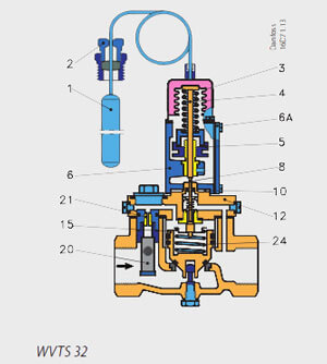
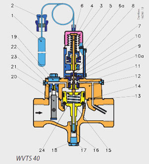
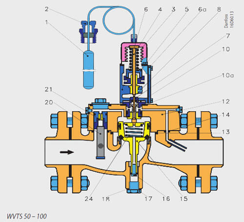 1.Sensor
2.Gland
3.Bellows element
4.Pressure rod
5.Regulating nut
6.Setting element housing
6a.Cover
7. Pilot orifice assembly
8. Pilot cone
10.Insulating washer
12.Valve cover
15.Servo piston
20.Filter cartridge (self-cleaning)
21.Equalising orifice
24.Servo spring
The valve body is made of cast iron with pressed-in bronze seat. The pilot orifice assembly (7) consists of a
housing with seat and pilot cone of stainless steel. A filter cartridge (20) is built into the valve cover. Here the equalising orifice is protected by a replaceable filter. The bellows in the bellows element (3) are of tin bronze. In designing WVTS, great emphasis was placed on producing a valve with a completely tight seat and no external
leakage. The servo piston was therefore fitted with a ring of special rubber that creates an elastic seal against the valve seat.
A specially designed rubber sleeve ensures that the servo piston moves in the cylinder with minimum friction.
External valve leakage is prevented at the pilot cone where the spindle is fitted with Teflon cup washers. Cover gaskets and pilot channel seals are rubber. The water-tight rubber seal between cover (6a) and housing (6) ensure that moisture cannot enter and freeze up the spindle. The insulating washer (10) prevents heat transmission between valve body and setting element housing.
Capacity
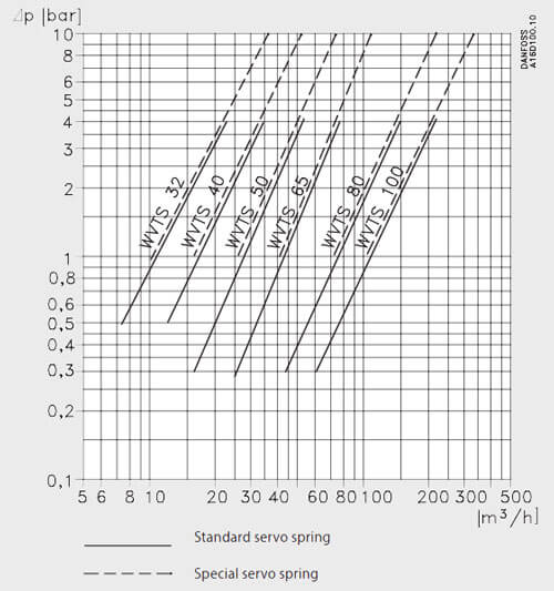
The capacity curves show the capacity (water quantity in m³/h) of the individual valve sizes as a function of pressure drop across the valve. The capacities are given for approx. 85% valve opening and are obtained with an offset of 4 °C (temperature rise at sensor) on both upper and lower temperature ranges.
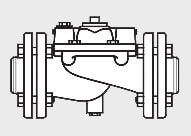
Dimensions [mm] and weights [kg]
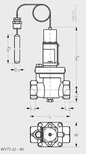
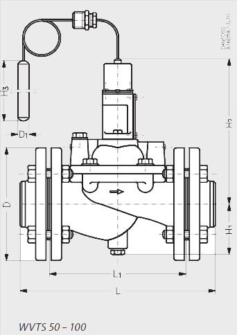
| Type | H1 | H2 | H3 | L | L1 | B | øD | øD1 | weight Net |
|---|---|---|---|---|---|---|---|---|---|
| WVTS 32 | 42 | 196 | 210 | 138 | 20 | 85 | 18 | 4 | |
| WVTS 40 | 72 | 224 | 210 | 198 | 30 | 100 | 18 | 7 | |
| WVTS 50 | 78 | 230 | 210 | 315 | 218 | 165 | 18 | 19 | |
| WVTS 65 | 82 | 246 | 210 | 320 | 224 | 185 | 18 | 24 | |
| WVTS 80 | 90 | 278 | 210 | 370 | 265 | 200 | 18 | 34 | |
| WVTS 100 | 100 | 298 | 210 | 430 | 315 | 220 | 18 | 44 |