VLT® AQUA Drive FC200 Fact Sheet
Optimized drive for AC motor driven water and waste water applications. User friendly setup makes installation
easy and enables owners to reach the highest level of performance and lowest cost of ownership.
Featuring a wide range of powerful, standard features, which can be expanded with performance improving options,
the VLT® AQUA Drive is equally suited to both new and retrofit projects.
Set up the drive quickly and easily with the user friendly quick menu. By collecting the most important water and pump parameters in one place, the risk of incorrect configuration is reduced significantly.
 Instantly benefit from high efficiency, fast payback and the lowest overall cost of ownership for water and waste water applications.
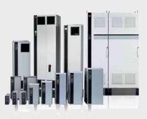
Power range:
1 x 200 – 240 V AC: …………… 1.1 – 22 kW
1 x 380 – 480 V AC: …………… 7.5 – 37 kW
3 x 200 – 240 V AC: …………. 0.25 – 45 kW
3 x 380 – 480 V AC: …….. 0.37 – 1000 kW
3 x 525 – 600 V AC: …………. 0.75 – 90 kW
3 x 525 – 690 V AC: …………11 – 1400 kW
| Feature | Benefit |
|---|---|
| Dedicated features | |
| Dry run detection | Protects the pump |
| Flow compensation function | Saves energy |
| 2 step ramps (initial/final ramp) | Protects deep well pumps |
| Check valve ramp | Protects against water hammering and saves installation cost for soft close valves |
| Pipe fill mode | Eliminates water hammering |
| Built-in motor alternation feature | Duty stand by operation, cost reduction |
| Sleep Mode | Saves energy |
| No/low flow detection | Protects the pump |
| End of pump-curve detection | Pump protection, leakage detection |
| Pump cascade controller | Lower equipment cost |
| Built-in Smart Logic Controller | Often makes PLC omissible |
| Deragging | Preventive/reactive pump cleaning |
| Back-channel cooling for frame D, E and F | Prolonged lifetime of electronics |
| Energy saving | Less operation cost |
| VLT® efficiency (98%) | Saves energy |
| Automatic Energy Optimisation (AEO) | Saves 3 – 8% energy |
| Auto Tuning of Staging Speeds | Smoothens the staging and saves energy |
| Reliable | Maximum uptime |
| IP 00 – IP 66 enclosures (depending on power size) | Choose the protection class you need |
| All power sizes available in IP 54/55 enclosures | Broad usability in standard enclosure |
| Password protection | Reliable operation |
| Mains disconnect switch | No need for external switch |
| Optional, built-in RFI suppression | No need for external modules |
| One Wire safe stop | Safe operation/less wiring |
| Max. ambient temperature up to 50°C without derating (D-frame 45°C) | Reduced need for cooling |
| User-friendly | Save initial and operation cost |
| One drive type for the full power range | Less learning required |
| Intuitive user interface | Time saved |
| Integrated Real Time Clock | Lower equipment cost |
| Modular design | Enables fast installation of options |
| Auto tuning of PI-controllers | Time saved |
| Payback time indication | Monitor performance |
Application options
Extend the functionality of the drive with integrated options:
VLT® General Purpose I/O MCB 101
3 digital inputs, 2 digital outputs, 1 analogue current output, 2 analogue voltage inputs.
VLT® Extended Cascade Controller MCO 101, VLT® Advanced Cascade Controller MCO 102
Upgrade the built-in cascade controller to operate more pumps with higher energy efficiency using master/follower
pump control. Run the pumps in use at the same speed and optimise staging speeds automatically during operation. Run time of all pumps is balanced to distribute wear and tear evenly.
VLT® Sensor Input MCB 114
Monitors the PT100/PT1000 and protects motors from overheating.
VLT® PTC Thermistor Card MCB 112
The MCB 112 is connected to safe stop and protects the motor from overheating. It is approved for controlling
a certified Ex proof motor in a potentially explosive atmosphere (ATEX) in zones 1 + 2 (gas) zones 21 + 22 (dust).
VLT® 24 V External Supply MCB 107
Back-up option to keep the control system alive during mains loss.
Coated PCB available
For harsh environments according to levels in IEC61721-3-3, standard 3C2, optional 3C3.
Relay & Analogue I/O option
(VLT® Relay Card MCB 105, VLT® Analog I/O MCB109) Flexible I/O options adding 3 relays or 3 analogue inputs and 3 analogue outputs respectively.
High power options
See the VLT® High Power Drive Selection Guide for a complete list.
Power options
Choose from a wide range of external
power options for use with our drive
in critical networks or applications:
■ VLT® Low Harmonic Drive:
Optimum reduction of harmonic distortion with built-in active filter.
■ VLT® Advanced Harmonic Filter:
For applications where reducing harmonic distortion is critical.
■ VLT® dU/dt filter:
Provides motor isolation protection.
■ VLT® Sine wave filter (LC filter):
For noiseless motor.
PC software tools
■ VLT® Motion Control Tool MCT 10
Ideal for commissioning and servicing the drive, including guided programming of cascade controller, real time clock, smart logic controller and preventive maintenance.
■ VLT® Energy Box
Comprehensive energy analysis tool. Energy consumption with and w/o drive can be calculated (drivepayback time). Online function for accessing drives energy log.
■ VLT® Motion Control Tool MCT 31
Harmonics calculations tool.
| Specifications | |
|---|---|
| Mains supply (L1, L2, L3) | |
| Supply voltage | 200 – 240 V ±10%, |
| Supply voltage | 380 – 480 V ±10%, |
| Supply voltage | 525 – 600 V ±10%, |
| Supply voltage | 525 – 690 V ±10% |
| Supply frequency | 50/60 Hz |
| Displacement Power Factor (cos φ) near unity | (> 0.98) |
| True power factor (l) | ≥ 0.9 |
| Switching on input supply L1, L2, L3 | 1 – 2 times/min. |
| Output data (U, V,W) | |
|---|---|
| Output voltage | 0 – 100% of supply |
| Switching on output | Unlimited |
| Ramp times | 0.1 – 3600 sec. |
| Output frequency (dependent on power size) | 590 Hz |
Note: VLT® AQUA Drive can provide 110% current for 1 minute. Higher overload rating is achieved by oversizing the drive.
| Digital inputs | |
|---|---|
| Programmable digital inputs | 6* |
| Logic | PNP or NPN |
| Voltage level | 0 – 24 V DC |
* Two of the inputs can be used as digital outputs.
| Analogue inputs | |
|---|---|
| Number of analogue inputs | 2 |
| Modes | Voltage or current |
| Voltage level | -10 to +10 V (scaleable) |
| Current level | 0/4 to 20 mA (scaleable) |
| Pulse inputs | |
|---|---|
| Programmable pulse inputs | 2 |
| Voltage level | 0 – 24 V DC (PNP positive logic) |
| Pulse input accuracy | (0.1 – 110 kHz) |
* Two of the digital inputs can be used for pulse inputs.
| Analogue output | |
|---|---|
| Programmable analogue outputs | 1 |
| Current range at analogue output | 0/4 – 20 mA |