Recitifiers
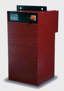
QUASAR 500 DC & DCR RECTIFIERS
QUASAR 500 is a line of switch-mode recti ers for surface treatment processes, electro-winning and water treatment. CRS recti ers use pulse width modulation (PWM) technique to control the current amplitude instead of the voltage. The result is a more accurate output current than other topologies.
 Electrical Features
- > High speed IGBT technology
- > Modular power platform and multi-tower interconnection
- > Microprocessor control based
- > Up to 40% power saving versus Silicon Controlled Recti er (SCR)
- > Cos Ø = 1
- > Low output current ripple
- > High precision voltage and current regulation (1000 steps)
- >Fast response time and high stability to load variation ( ~1ms)
Hardware Features
- > 15 to 170 cm height
- > 43 * 43 cm base size
- > Light weight
- > Main switch and operator panel in the front
- >All input/output connections in the back for easy access
 Software Features
- > Simple waveform programming from the operator panel
- (output current, voltage, cycle time and ramp time)
- > Custom software available
- > Simultaneous current and voltage regulation
- > A/hr and A/min meters for precise thickness and solution-feed pumps control
Operation modes
- > Manual
- > Automatic (Via PC, PLC, Pro bus-DP, DeviceNet, etc.)
- > Remote control
2 Year Warranty
| Most common applications | Output voltage [V]1 | Max. output current per tower [A] Air | Max. output current per tower [A] Water | ||
|---|---|---|---|---|---|
| Direct Current | DC – Direct Current (forward) | Barrel process control | 8/10 | 5000 | 8000 |
| Barrel process control | 12 | 5000 | 6000 | ||
| Static method (jig) based processes | 16 | 5000 | 5000 | ||
| Zinc alloy deposition | 18 | 4000 | 4250 | ||
| Anodizing | 20 | 3200 | 4000 | ||
| Hard Anodizing | 25 | 3200 | 3000 | ||
| Electro-winning | 30 | 2600 | 2500 | ||
| Electro-polishing | 40 | 2000 | 2000 | ||
| Electro-static painting | 50 | 1500 | 1500 | ||
| Metal stripping | 60 | 1300 | 1250 | ||
| 100 | 650 | 800 |
| DCR – Direct Current Reverse (forward and reverse) | Hard chroming, Alkaline copper, Electro-cleaning | 8 /10 / 16 / 18 / 20 / 25 / 30 / 40 / 50 | 8 power modules (including reverse units) |
| Technical Specications | ||
|---|---|---|
| ELECTRICAL SPECIFICATIONS | ||
| Output | Power – DC type | Up to 400 kVA / 4 towers (Max. 8 power modules per tower) |
| Power – DCR type | 1 tower (Max. 8 power modules – including reverse units) | |
| Voltage – DC type | From 8 to 100 V | |
| Voltage – DC type | From 8 to 100 V | |
| Voltage – DCR type | From 8 to 50 V | |
| Hardware control method | Current control | |
| Control accuracy | 1/1000 of max. current or voltage | |
| Current regulation range | 5 – 100% of max. current | |
| Voltage regulation range | 20 – 100% of max. voltage | |
| Current ripple – All con g. | < 0.5% or < 3.5% of regulation range depending on output capacitors | |
| Current ripple – MINI (Con g. 01) | < 2% of regulation range | |
| E ciency | 87% (typ.) | |
| Regulation speed – Software | 10%-90% in 100 ms with 500 ms reverse dead time | |
| (forward or reverse) – Hardware | 10%-90% in 20 ms with 500 ms reverse dead time | |
| Power Factor | > 93% | |
| Secondary withstand voltage | 500 Vac, 1′ between secondary and ground | |
| Input | Mains voltage | 230 / 380 / 440 / 500 Vac +/- 10% |
| Mains frequency | 50/60 Hz | |
| Phase number | 3 | |
| Neutral | NOT USED | |
| Primary current | Max. 160 A per tower | |
| Leakage current | See EMC input lter speci cations | |
| Primary withstand voltage | 2000 Vac 50Hz, 1′ between primary and secondary and primary and ground |
| GENERAL SPECIFICATIONS | ||
|---|---|---|
| Switching Technology | PWM IGBT | |
| Cooling Systems | Air / Water | |
| Operation Conditions | Location | Indoor use only |
| Environment temperature | 0 – 40 °C | |
| Relative humidity | 15- 85% not condensing | |
| Filter obstruction – air cooled | 15% max. | |
| Water input temp. – water cooled | 19-22 °C | |
| Altitude | <= 1000 m | |
| Con guration | Stand alone | DC and DCR type |
| Multi-tower | DC type | |
| Degree of Protection | Air cooled | IP33 |
| Water cooled | IP43 | |
| Conformity of EU Directives | 2006/95/EC – Low Voltage Directive | |
| 2004/108/EC – Electromagnetic Compatibility | ||
| 2006/42/EC – Machines Directive |
| SERIAL INTERFACE | |
|---|---|
| Communication Ports | |
| RS232 | RS485 |
| Communication Protocols | |
| CRS-ASCII | RS232 point-to-point and RS485 network |
| Modbus-RTU | RS232 point-to-point and RS485 network |
| Pro bus-DP (On request) | Pro bus-DP network |
| DeviceNet (On request) | CAN bus network |
| PROTECTION | ||
|---|---|---|
| Input Over Voltage | ||
| Software selectable | ||
| Surge | ||
| According to directive | EN 61000-4-5 | |
| Programmed limit | 2 kV between each input phase and PE. 1 kV across each input phase combination. |
|
| Thermal Protection | ||
| With PTC on each module | ||
| Output Short Circuit | ||
| Type | Hardware | Software |
| Programmed limit | Iout max | 25% of Iout max |
| Detection time | 20 ms | 100 ms |
| Phase Loss | ||
| Type | Hardware | Software |
| Programmed limit | Half cycle | Amplitude <10% |
| FULL LOAD HARMONICS DISTORTION | ||
|---|---|---|
| Class | Absorbed Current Distortions | |
| 3o. | 150 Hz | |
| 5o. | 250 Hz | < 22.5 % |
| 7o. | 350 Hz | < 12.5 % |
| 9o | 450 Hz | |
| 11o. | 550 Hz | < 11.0 % |
| 13o. | 650 Hz | < 7.6 % |
| 17o. | 850 Hz | < 8.0 % |
| 19o. | 950 Hz | < 4.8 % |
| THD | THD | MAX 30% |
