VLT® AutomationDrive
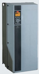 The VLT® AutomationDrive is extremely configurable and represents a drive concept covering the whole production or machine.
The make-through modular design makes upgrade easy as well as adaptation of future features.
On-board manuals make operation easy and the built in Smart Logic Control allows for basic programming covering many common PLC functions.
Pluggable options
Numerous I/O options, fieldbus options and programmable extensions are available, mounted and
tested from factory or to plug in for changeover or upgrade.
Awarded VLT® Automation drive was given the Frost & Sullivan award for innovation and the iF design award for its
user friendliness.
The perfect solution for:
• Industrial automation
• High dynamic applications
• Safety installations
Power range
0.25 – 37 kW (200 – 240 V)
0.75 – 1000 kW (525 – 600 V)
11 – 1000 kW (600 – 690 V)
With 110% overload torque (normal overload)
| Features | Benefits |
|---|---|
| Reliable | -maximum up-time |
| . One wire safety terminal | . Suitable for cat. 3 safety installations |
| . Available in IP 66 enclosures | . suitable for harsh and wash down areas |
| . Ambient temperature 50°C without derating | . less need for cooling or oversizing |
| User friendly | -save commissioning and operating cost |
| . Pluggable options | . Easy upgrade and change over |
| . Awarded control panel | . userfriendly |
| . Onboard manual | . easy operation |
| . Spring loaded cage clamps | . Optimum process control |
| . Pluggable terminals | . Easy connection |
| Innovative | – save time and money |
| . Modular design | . flexibility |
| . Smart Logic Control | . replace expensive PLC |
| . Safety terminal | . suitable for cat. 3 safety applications |
| . Pluggable options | . Easy upgrade and charge over |
| . Intelligent heat management | . excess heat effectively removed |
| Specifications | |
|---|---|
| Main supply (L1, L2, L3): | |
| Supply voltage | 200-240V, 380-480V, 380-500V, 525-600V +/-10% |
| Supply frequency | 50/60 Hz |
| True Power Factor ( ) | 0.92 nominal at rated load |
| Switching on input supply L1, L2, L3 (power-ups) | maximum 2 times/min. |
| Digital inputs: | |
| Programmable digital inputs | FC 301:4(5)/FC 302:4(6) |
| Logic | PNP or NPN |
| Voltage level | 0-24VDC |
| Analogue inputs: | |
| Number of analogue inputs | 2 |
| Modes | Voltage or current |
| Voltage level | FC 301:0 to + 10/FC 302:-10 to + 10V (scaleable) |
| Pulse/encoder inputs: | |
| Programmable pulse/encoder inputs | 2/1 |
| Voltage level | see section on Digital input |
| Maximium voltage on input | 28V DC |
| Digital output: | |
| Programmable digital/pulse outputs | 2 |
| Voltage level at digital/frequency output | 0-24V |
| Relay outputs: | |
| Programmable relay outputs | FC 301:1/FC 302:2 |
| Cable lengths and cross sections: | |
| Max. motor cable length: | |
| screened/armoured | FC 301:50m/FC 302: 150m |
| unscreened/unarmoured | FC 301:75m/FC 302:300m |
Options
Synchronizing and positioning – The Synchronizing Controller and positioning controller expands the functional properties and offers a
host of user-friendly benefits based on thought-through and innovative features
MCB 112 PTC Relay Card – Stops the motor in case of overheating (signal from sensor) and resume operation when the temperature is normal.
Sine-Wave Filters – Optimize the motor power current providing a sinusoidal phase-to-phase motor voltage. They reduce motor insulation stress, acoustic noise, and bearing currents.
dU/dt Filters – Eliminate very fast voltage changes to reduce the motor insulations stress. Are recommended in applications with older motors, aggressive environments or frequent braking.
Disconnect switch

| Cabinet | sizes [mm] | ||||||||||||
|---|---|---|---|---|---|---|---|---|---|---|---|---|---|
| IP20 and | IP21 / NEMA1 | ||||||||||||
| Enclosure name | A1* | A2 | A3 | B1 | B2 | C1 | C2 | D1 | D2 | E1 | E2 | E3 | |
| Power range [KW] | Min: | 0.25 | 0.25 | 3 | 5.5 | 11 | 15 | 22 | 90 | 132 | 250 | 450 | 710 |
| Power range [KW] | Max: | 1.5 | 5.5 | 7.5 | 18.5 | 30 | 45 | 90 | 132 | 315 | 560 | 710 | 1000 |
| Height | IP20 | 200 | 268 | 268 | 481 | 651 | 680 | 770 | 1159 | 1540 | 2000 | 2000 | 2000 |
| Height | IP21 / NEMA1 | 307 | 370 | 370 | 481 | 651 | 680 | 770 | 1159 | 1540 | 2000 | 2000 | 2000 |
| Width | without option C | 75 | 90 | 130 | 242 | 242 | 308 | 370 | 420 | 420 | 600 | 1400 | 1600 |
| Width | with slim option C | 130 | 170 | 242 | 242 | 308 | 370 | 420 | 420 | 600 | 1400 | 1600 | |
| Width | with wide option C | 1550 | 190 | 242 | 242 | 308 | 370 | 420 | 420 | 600 | 1400 | 1600 | |
| Depth | without option A or B | 205 | 205 | 205 | 261 | 261 | 310 | 335 | 373 | 373 | 494 | 600 | 600 |
| Depth | with option A or B | 219 | 219 | 219 | 261 | 261 | 310 | 335 | 373 | 373 | 494 | 600 | 600 |
| IPS4/IPS5/IP66/NEMA12 | ||||||||||
|---|---|---|---|---|---|---|---|---|---|---|
| Enclosure name | A5 | B1 | B2 | C1 | C2 | D1 | D2 | E1 | E2 | E3 |
| Height | 420 | 481 | 651 | 680 | 770 | 1159 | 1540 | 2000 | 2000 | 2000 |
| Width | 242 | 242 | 242 | 308 | 370 | 420 | 420 | 600 | 1400 | 1600 |
| Depth | 200 | 261 | 261 | 310 | 335 | 373 | 373 | 494 | 600 | 600 |
| IPOO/Chassis | ||||
|---|---|---|---|---|
| Enclosure | name | D1 | D2 | E1 |
| Height | 997 | 1277 | 1499 | |
| Height | without option C, with slim option C and with wide option C | 408 | 408 | 585 |
| Depth | without option A or B | 373 | 373 | 494 |
| Depth | with option A or B | 373 | 373 | 494 |